Ferrous Gearing
Ferrous materials for gearing include carbon and alloy wrought and cast steels, cast iron and ductile irons. Gearing of alloy and carbon steel is manufactured from different forms of rough stock depending upon service, size, design, quantity, availability, and economic considerations. These forms include wrought steel, weld fabrications and castings.
Wrought Steel. Wrought steel is the generic term applied tocarbon and alloy steels which are mechanically worked into form for specific applications. The standard wrought steel forms are round stock, flat stock and forgings. Forgings reduce machining time, and are available in a wide range of sizes and grades.
- Round Stock. Round bars can be purchased in various diameters for standard carbon and alloy grades. They are typically available as hot rolled, hot rolled-cold drawn, hot rolled-cold finished and forged rounds. Cold drawing produces a close tolerance bar with improved mechanical properties(higher hardness and yield strength). Low to medium carbon steels are normally available as cold drawn bar for gearing. Hot rolled---cold finished bars are machined (turned, ground and/or polished) for improved size control, but show no improvement in mechanical properties over hot rolled or annealed bar. Hot rolled bars are mechanically worked at approximately 2100-2400_F (1150-1315_C) and may be subsequently annealed, straightened and stress relieved. Forged round bars are forged round under a press or hammer at the same approximate temperature as hot rolled bars (higher temperature for lower carbon content carbon or alloy steel) and are manufactured to a size larger than can be formed with rolling dies or rolls. Forged round bars can be purchased in a variety of heat treat conditions depending upon application.
Hot rolled bars are also now manufactured from continuous cast steel bar manufactured with continuous casters. Continuous cast bar is subsequently hot rolled with sufficient reduction in cross sectional area (7 to 1 minimum) during hot deformation to produce densification and quality bar for many gearing applications.
Approximate maximum diameter of the various types of round stock, depending upon steel mill capacity, is as follows:
Hot Rolled: 8.0 inch (205 mm)
Cold Drawn: 4.0 inch (100 mm)
Cold Finished: 5.0 inch (125 mm)
Forged Round: 16.0 inch (405 mm) - Flat or Plate. Commercial flat or plate steel of numerous carbon and alloy grades is available in standard thicknesses in a wide range of widths and lengths. Flat stock is typically available in hot rolled or hot rolled and annealed conditions.
Forgings. Forgings are made by hot mechanical deformation (working of a steel billet into a specific form) which densifies the structure, and may provide improved inclusion orientation. Typically, deformation is done while the billet is at temperatures generally above 1900_F(1038_C).
Cast ingots, from which blooms and billets are manufactured prior to forming forgings and bar stock, are now also bottom poured as well as conventional top poured. Bottom poured ingots are poured
with a bottom ingate and runner which provide smolten steel to the ingot mold, much like steel castings are produced. Bottom poured ingots show improved macro-cleanliness and ingot yield (more usable ingot metal after conventional cropping or removal of the top pipe cavity and bottom discard of top poured ingots).
Alloy steel, manufactured by electric furnace practice using part or all of the cleanliness techniques discussed in 4.3, can result in improved transverse ductility and impact strength. Forging stock is always fully killed steel to minimize the occurrence of fissures due to dissolved gases during the forging process.
The standard forging classifications are:- Open Die Forging. This method produces a rough dimensioned piece by mechanical deformation between an upper and lower die (hammer and anvil) in an open frame press or hammer. Open die forgings may be specified to be upset forged to increase center densification. An upset forging is produced when the billet is initially hot worked in one direction, and then is rotated 90 degrees and hot worked again. Upset forgings are often used for critical high speed gearing, greater than 30,000 feet/minute (152 m/sec) pitch line velocity, which develop high centrifugal stress at the center.
- Closed Die Forging. This method produces a closer toleranced piece, generally smaller than an open die forging. The upper and lower dies trap the steel billet in a closed (confined) cavity and the press action deforms the metal to fill the die cavity, producing a more exact contoured forging.
- Rolled Ring Forging. This method produces a donut---shaped work piece. Typically the process involves piercing a pancake-shaped billet with a mandrel and shaping the ring by a hammer action between the mandrel and the press anvil. Large diameter rings are rolled on a roller press from circular billets containing a central hole
- Weld Fabrications. Weld fabricated gears generally consist of rolled or forged rings, formed plate or castings for the rim(tooth) section, a forged or cast hub and mild steel plate for the web or arm support sections. The rim or tooth section is heat treated to obtain specified hardness (mechanical properties) prior to weld assembly. After weld assembly, using appropriate preheat and postheat temperatures, welded assemblies are furnace stress relieved at 950-1250_F (510-675_C) depending upon the previous tempering temperature used to obtain the specified hardness of the rim section. ASTMA290 should be referenced for ring forgings for fabricated gears.
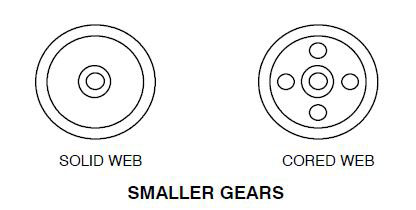
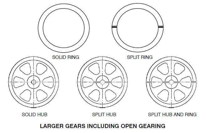
- Cast Steels. Carbon and alloy steel castings are used for a wide variety of through hardened gearing and, to a lesser degree, for case hardened applications. The size of cast gearing varies from 10.0 inch(254 mm) outside diameter with a 2.0 inch (51 mm) face width for solid rim gears, to split ring gears about 480 inch (12 192mm) outside diameter with a 40 inch (1016 mm) face. Smaller gears generally have a solid web and hub design, with possible cored holes in the web or flange for weight reduction. Larger gears are usually solid hub, split hub, or split hub and rim design, which incorporate cast arms rather than the heavier solid web design used for smaller gears. Still larger ring gears are solid or split ring design with bolt holes at the splits and on the inside diameter flange for gear assembly and mounting purposes. Split gears are cast in two or four segments. Typical cast gear designs are shown as follows:
- Manufacture. Cast steel is manufactured by the open hearth, electric arc, or induction furnace melting processes, using both acid or basic lined furnace steel making practices. Secondary refining processes can be used for reducing the gas, phosphorus, and sulfur levels of cast steel.
- Material Grades of Cast Steel. The material grades used for cast gearing are generally modifications (silicon, etc) of standard AISI or SAE designations. Through hardened gearing applications generally use 1045, 4135, 4140, 8630, 8640, and 4340 type steels. Carburizing grades are usually 1020, 8620 and 4320 types. As with wrought steel, care must be taken to ensure that the specified cast analysis for through hardened gearing has sufficient hardenability to obtain the specified minimum hardness.
- Repair Welding of Cast Steel. Repair welding of castings prior to heat treatment is routinely performed by the casting producer. Repairs in the rim (tooth) portion and other critical load bearing locations should be performed only prior to heat treatment. Heat treatable electrodes should be used for repairing prior to heat treatment in order to produce hardness equivalent to the base metal after heat treatment. Repair welding, if allowed after heat treatment, shall be followed by reheat treatment, whenever possible. If reheat treatment is not possible, localized preheat and post heat are recommended to avoid or minimize unfavorable residual tensile stress or high hardness in the heat affected zone. All welds should be inspected to the same quality standard used to inspect the casting.
- Heat Treatment of Cast Steel. Castings are heat treated to either a specified hardness or to specified hardness and minimum mechanical properties. The minimum number of hardness tests required on both rim faces of gear castings is generally based on the outside diameter. The number of tests increases with OD size.
- Quality of Cast Steel. Castings should be furnished free of sand, scale, extraneous appendages, and hard areas resulting from arc---airing, gas cutting, and repair welding which could adversely affect machining. Casting should also be free of cracks, hot tears, chills, and unfused chaplets in the rim section. Castings must meet the nondestructive test requirements in the rim section. The quality specified in other than the rim (tooth) section is often less stringent. Minor discontinuities in finish machined teeth, if present, are often contour ground for removal, in preference to cosmetic weld repair. Approval by the customer may be required.
Dry or wet fluorescent magnetic particle inspections are routinely performed to meet specified surface quality requirements. Other nondestructive testing, such as radiograph and ultrasonic inspection, is performed to evaluate internal integrity of the rim (tooth) section when specified. Methods of testing, test locations, and acceptance standards are established between the purchaser and manufacturer.
- Cast Iron. Cast Iron is the generic term for the family of high carbon, silicon, iron alloys. The family of cast irons is classified by the following categories.
- Gray Iron. Gray iron contains (typically over 3.0 percent) carbon, which is present as graphite flakes. It is characterized by the gray color occurring on a fracture surface.
- Material considerations. Cast irons for gears are made by the electric arc furnace, cupola, or induction practice and should be free of shrink, porosity, gas holes, entrapped sand and hard areas in the tooth portion.
Repair welds in areas to be machined should have machinability equivalent to the casting. Repair welds in the tooth portion should only be performed with the approval of the gear purchaser. - Heat Treating. Cast iron castings are generally furnished as cast unless otherwise specified. Stress relieving may be deemed necessary to hold close dimensional tolerances. It is recommended that castings be heated to 1000 to 1100_F(538-593_C), holding at temperature up to one hour per inch of maximum section and furnace cooled to below 600_F (315_C).
- Chemical Analysis. Unless otherwise specified, the chemical analysis is left to the discretion of the casting supplier as necessary to produce castings to the specification.
- Mechanical Properties. Cast iron gears are rated according to AGMA practice based on hardness. Therefore, hardness determines the rating of the gear.
- Material considerations. Cast irons for gears are made by the electric arc furnace, cupola, or induction practice and should be free of shrink, porosity, gas holes, entrapped sand and hard areas in the tooth portion.
- Ductile Iron. Ductile iron, sometimes referred to as nodular iron, is characterized by the spheroidal shape of the graphite in the metal matrix, produced by innoculation with magnesium and rare earth elements. A wide range of mechanical properties are produced through control of the alloying elements and subsequent heat treatments.
- Material Considerations. Ductile iron castings are made by the electric arc furnace, cupola or induction practice and should be free of shrink, porosity, gas holes and entrapped sand and hard areas in the tooth portion.
Repair welds in areas to be machined should have equivalent machinability as the casting. Repair welding in the tooth portion should only be performed with the approval of the gear purchaser. - Heat Treating. Ductile iron castings shall be heat treated by annealing, normalizing and tempering or quenching and tempering or as---cast as required to meet the specified mechanical properties. These heat treatments produce ferritic, pearlitic or martensitic structures.
- Chemical Analysis. Unless otherwise specified, the chemical analysis is left to the discretion of the casting supplier as necessary to produce castings to the specification.
- Mechanical Properties. Typical mechanical properties are shown in Table 4---9.Other properties may be as agreed upon by the gear manufacturer and casting producer. Tensile test coupons
- Material Considerations. Ductile iron castings are made by the electric arc furnace, cupola or induction practice and should be free of shrink, porosity, gas holes and entrapped sand and hard areas in the tooth portion.
- Austempered Ductile Iron. Austempered Ductile Iron (ADI) is a ductile iron with higher strength and hardness than conventional ductile irons. The higher properties of ADI are achieved by closely controlled chemistry and an austempering heat treatment. This treatment results in a unique microstructure of bainitic ferrite and larger amounts of carbon stabilized austenite. With variation in austempering temperature and transformation time, several ranges of engineering properties can be achieved.
- Malleable Iron. Malleable iron is a heat treated white (chilled) iron which can be produced with a range of mechanical properties depending on the alloying practice and heat treatment. This has generally been replaced by ductile iron.
- Gray Iron. Gray iron contains (typically over 3.0 percent) carbon, which is present as graphite flakes. It is characterized by the gray color occurring on a fracture surface.
- Powder Metal (P/M). Powder metal parts are formed by compressing metal powders in a die cavity and heating (sintering) the resultant compact to metallurgically bond the powder particles. Secondary operations such as repressing or sizing may be used to obtain precise control of shape and size or to improve mechanical properties.
The powder metal process is used to reduce cost by eliminating machining operations, provide accurate dimensional control over large production runs, and obtain characteristics and shapes difficult to obtain by other methods. However, because of molding die costs, high production quantities are usually necessary to realize savings.
Although several powder metal materials are available, alloy steel is usually specified for gear applications.
“As sintered” alloy steels have a tensile strength range of 40---80 ksi (275---550MPa), with an elongation of 4.0 percent or less and an apparent hardness of HRB 60---85. Heat treated powder metal alloys have tensile strengths of 100 to 170 ksi (690---1170 MPa)with elongations of 1.0 percent or less, depending on density and alloy selected.
Density is the most significant characteristic of powder metal materials. For a given composition, mechanical properties are proportional to density; i.e., higher strengths are achieved at higher density levels. In recent years, powder metal processes have improved to the point where a typical density of 7.0 to 7.4 g/cm# can be achieved using secondary operations.
The ductility of powder metal parts is substantially lower than for wrought steels. Hardness specifications can be developed for powder metal parts, but must be specified as “apparent hardness” since the hardness value obtained using a standard tester (either HRB or HRC) is a combination of the powder particle hardness and porosity. The actual hardness of the powder metal material will be higher than the apparent hardness reading and can be more accurately determined using special microhardness measurement techniques.
Parts can be heat treated after sintering, but must be processed in a controlled atmosphere to prevent changes in surface chemistry. Carburizing and carbonitriding can be performed, but products with a density under 6.8 g/cm# will not develop a definite case due to the ease of diffusion through the more porous lower density material. Penetration hardness testing cannot be correlated to material strength, but parts will achieve a file hard surface. Salt baths and water quench systems should be avoided. Further improvements in strength can be achieved by the use of hot forming powder metal. Powder metal preforms are heated to forging temperature and finished forged to final shape and density.
Parts processed in this manner have strengths and mechanical properties approaching the properties of wrought materials. Although this process is much more costly than the conventional powder metal process, it can still be cost effective for high production parts requiring higher mechanical properties than achievable using the standard process.
The controlled porosity in powder metal parts permits their impregnation with oil to provide a self lubricating part, especially for the internal type of gears.
The powder metal process is well---suited to the production of gears for several reasons:- Carbide dies provide consistent part accuracy over long runs.
- Retention of some porosity contributes to quietly running gears and allows for self---lubrication.
- Powder metal gears can be made with blind corners, thus eliminating undercut relief that is needed with cut gears, and have extra support strength at the blind end.
- Powder metal gears can be combined with other parts such as cams, ratchets, other gears, and assorted components.
Spur gears are the easiest to produce out of powder metal because of the vertical action of the press and ease of ejection of the perform from the die cavity before sintering. Bevel, miter, helical, and other special gear forms are, however, possible in powder metal with sufficient development. True involute gears are less difficult and may be less costly to pro duce in sufficient quantities than by other methods because tooth configuration is not a limitation.
- Other Ferrous Materials. In addition to materials used for gears which are described in this Manual there are other ferrous materials used for gears. These include hot work tool steel (H series), high speed steels, austenitic, martensitic and precipitation hardening stainless steels, etc. Special gear analyses are frequently used in applications with very high strength requirements.